


List of resistance selection models and online purchase address:Click on the image to enter

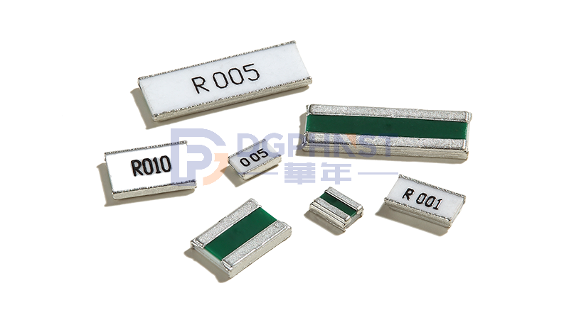
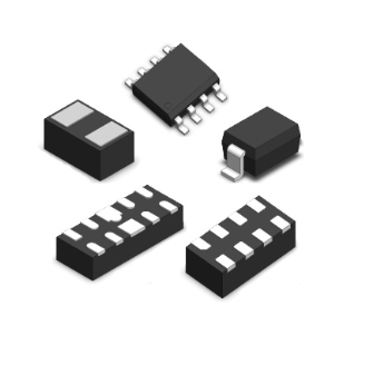
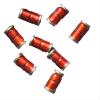
SMD resistors are a common electronic component widely used in electronic devices. It has the advantages of being compact, lightweight, easy to install, and higher density, therefore it has been widely used in modern electronic products. However, due to the small volume and unclear identification of SMD resistors, it is easy to cause recognition difficulties. This article will introduce several commonly used methods for identifying chip resistors to help readers better identify chip resistors.
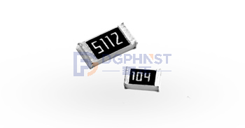
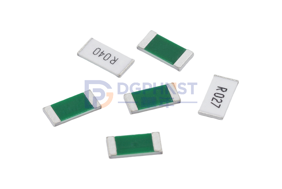
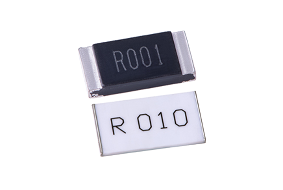
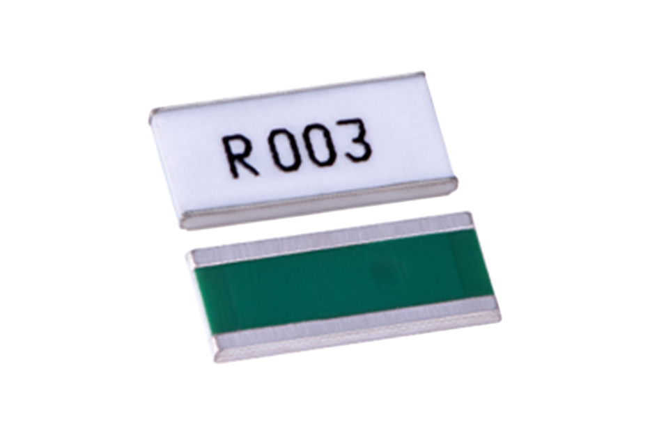
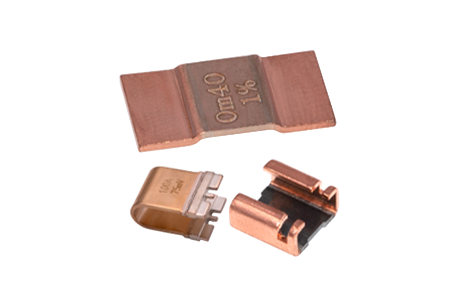
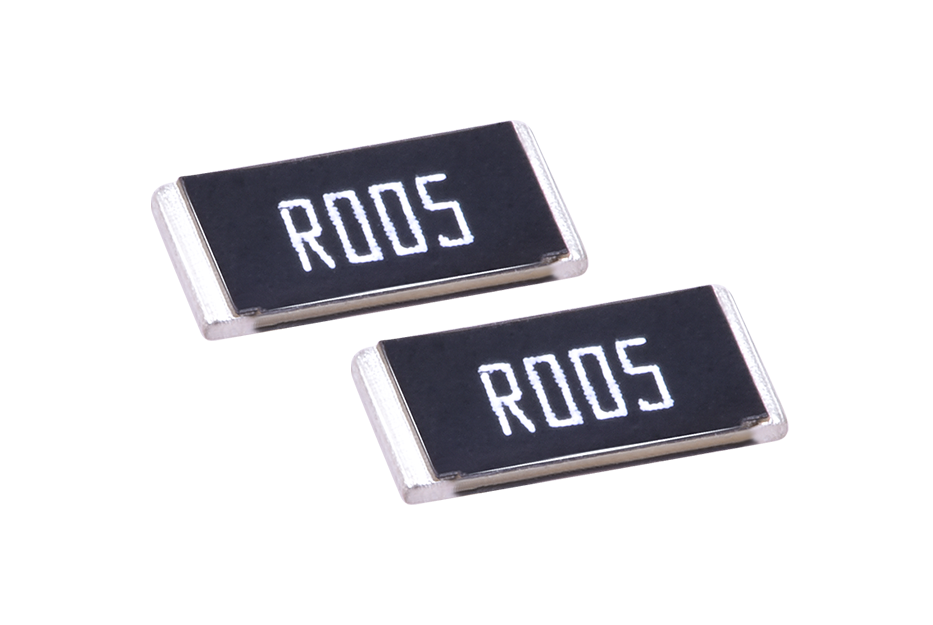
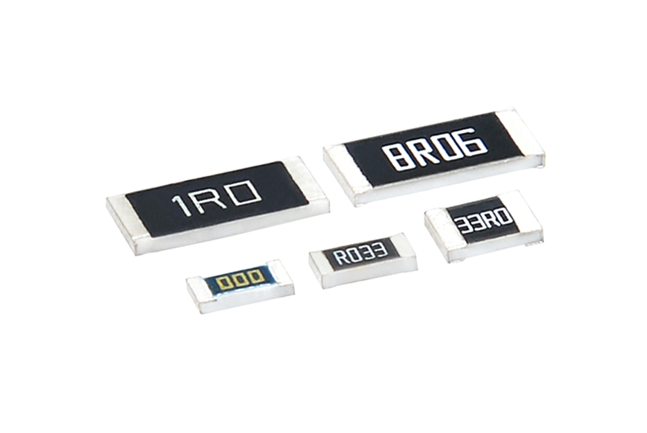
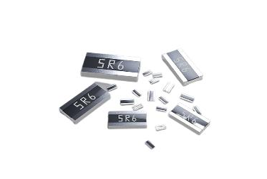
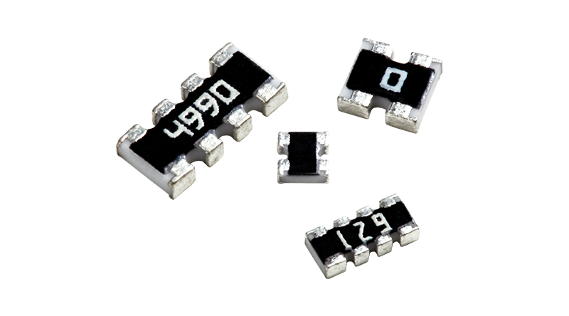
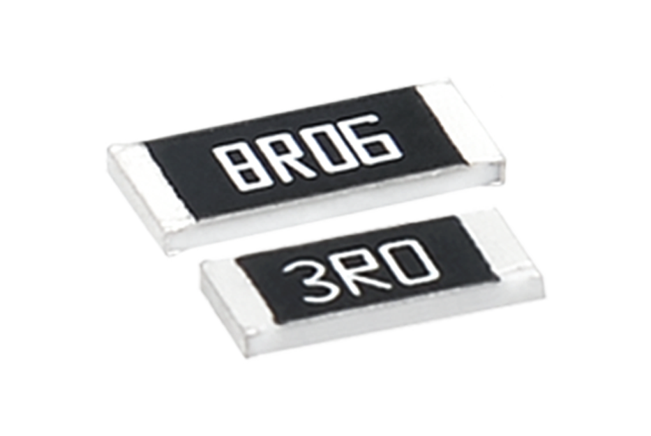
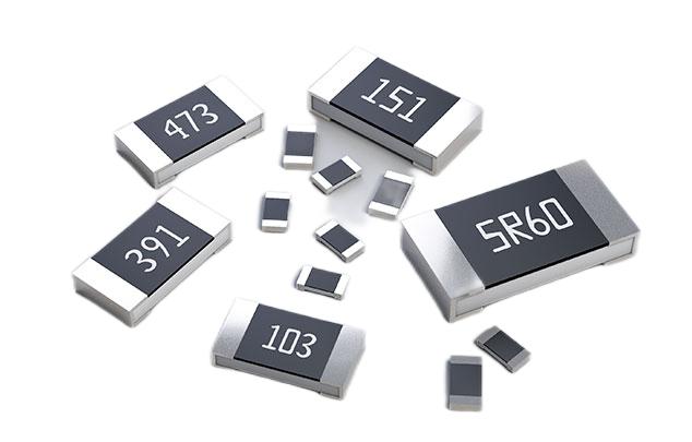
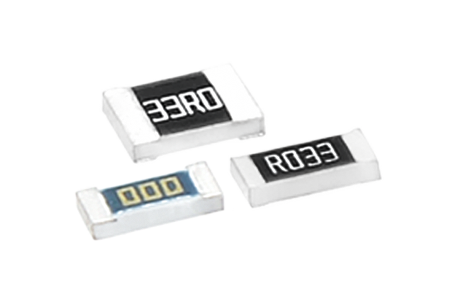
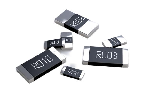
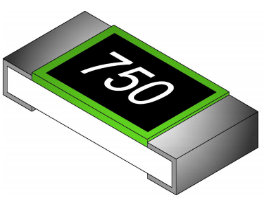
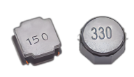
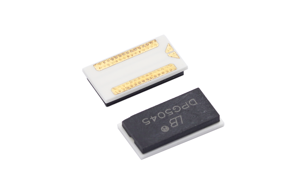
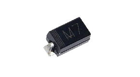
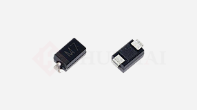
Printing identification method: Chip resistors usually have relevant information printed on their surface, such as resistance value, accuracy, temperature coefficient, etc. Through these markings, we can easily identify patch resistors. Generally speaking, the resistance value is represented by a number and a unit, such as "100" representing 100 ohms, "1K" representing 1 kiloohm, and "1M" representing 1 megaohm. Common units include ohms (Ω), kiloohms (K Ω), megaohms (M Ω), etc. The accuracy is often expressed as a percentage, such as "1%" representing an accuracy of 1%. In addition, the temperature coefficient is often represented by a three digit number, such as "100" representing a temperature coefficient of 100ppm/℃. By carefully observing these markings, we can easily identify the relevant information of the chip resistor.
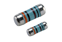
The color coding method for patch resistors is similar to the color coding method for traditional plug-in resistors. Usually, patch resistors have several circular color stripes, each representing a number. We can obtain the resistance value by comparing the numbers corresponding to the color stripes. Generally speaking, patch resistors marked with three color stripes can represent two digits, while patch resistors marked with four color stripes can represent three digits. The order of color stripes is from left to right, and the rightmost color stripe represents multiplying by a power of 10. For example, if the color stripes of red, blue, black, and gold represent "2", "6", "0", "5", the resistance value is 2605 ohms. By mastering the color coding rules of patch resistors, we can quickly and accurately identify the resistance value of patch resistors.
If the above methods cannot accurately identify the chip resistance using a resistance measuring instrument, we can use a resistance measuring instrument for measurement. Place the two probes of the resistance measuring instrument in contact with both ends of the patch resistance, and the measuring instrument will display the resistance value. This method is applicable to special patch resistors that cannot be identified by identification or color coding. However, it should be noted that when using a resistance measuring instrument for measurement, the chip resistor should be removed from the circuit board to prevent other electronic components from interfering with the measurement results.
Refer to the circuit diagram and component list. In the circuit diagram and component list of some electronic devices, detailed information about each component, including the model and value of the chip resistor, will be listed. If relevant circuit diagrams and component lists can be obtained, it is convenient to determine the model and value of the chip resistor through comparison.
In summary, identifying patch resistors requires a combination of various methods and techniques, including printing identification, color coding, using resistance measuring instruments, and referring to circuit diagrams. By proficiently mastering and flexibly applying these methods, we can easily and accurately identify chip resistors, improve work efficiency and quality.