


What is PoC?
PoC is the abbreviation for Power over Coax, which is a transmission method that achieves power without the need to prepare a dedicated power cable by overlaying a power supply on a signal cable.
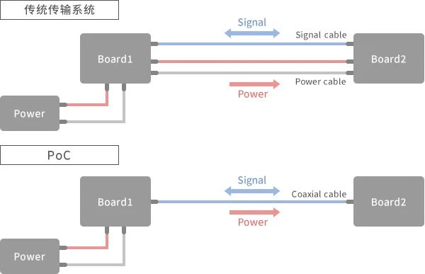
The difference between traditional transmission systems and PoC
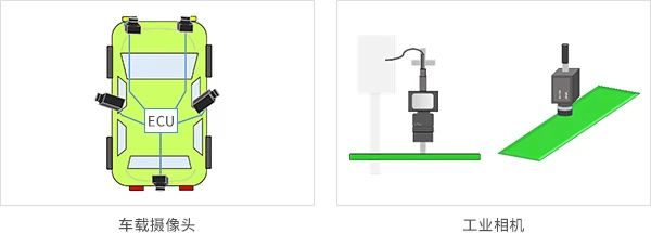
PoC is used in automobiles and industrial equipment. Used in cars for ADAS and proximity cameras, it helps simplify wiring design and reduce the weight of wiring harnesses;
Used in industrial equipment such as visual inspection cameras, spacious production lines require longer cables, but the use of PoC can reduce the number of cables and simplify wiring.
PoC System Application Example
PoC System Application Example
PoC is commonly used for the SerDes interface, where the serializer and deserializer are connected through coaxial cables.
On this coaxial cable, high-frequency signals and DC currents are superimposed together.
In this case, a bias T circuit will be configured to prevent high-frequency signals from serializing into the power line or DC current from flowing into the deserializer.
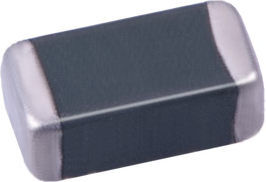
In the bias T circuit, capacitors are used to block DC and simultaneously pass high-frequency signals, as well as coils that block high-frequency signals and simultaneously pass DC signals.
In this article, capacitors used for bias T circuits are referred to as bias T capacitors.
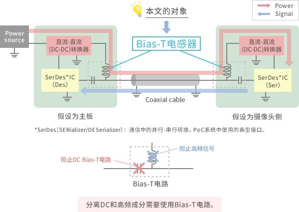
Typical Circuit Composition of PoC System
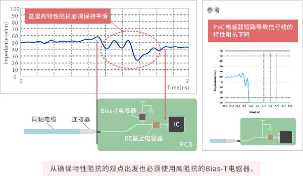
Due to the function of the Bias-T inductor to block AC and pass through DC, it must have high impedance. If the impedance is too low, the AC signal component will leak into the power line, and the signal component transmitted along the coaxial cable will decay.
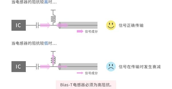
Characteristics required for Bias-T inductors: must have high impedance
We investigated the effect of Bias-T inductors on the characteristic impedance of signal lines. Connect the network analyzer to a substrate equipped with a SerDes IC or Bias-T circuit and measure the characteristic impedance using the TDR method (as shown in the figure below).
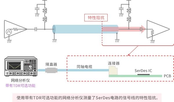
Measure the characteristic impedance of the signal line, and the results are shown in the following figure. The characteristic impedance of the transmission line varies depending on the wiring design of the substrate and the position of the components. By suppressing this change and keeping it smooth, the transmission characteristics will be improved. To maintain smoothness, the impedance of the Bias-T inductor must be sufficiently high. Because if the impedance of the Bias-T inductor is low, the characteristic impedance of the transmission line will decrease. The following figure (right) shows an extreme example of replacing the Bias-T inductor with a short-circuit strip. It can be confirmed that the characteristic impedance rapidly changes from 50 ohms to 0 ohms.
Measure the characteristic impedance of the signal line
The Influence of Bias-T Circuit on SI
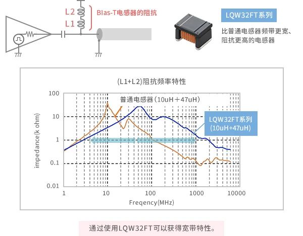
The Bias-T inductor also needs to have a wide frequency range.
The ideal impedance of an inductor increases proportionally to the frequency, but this is not the case with actual inductors. The impedance curve is parabolic in shape.
In order to find out at which frequency the Bias-T inductor used for PoC needs to have a higher impedance, we measured the signal components of SerDes on the frequency axis (as shown in the figure below). It was found that the signal distribution of SerDes is over a wide frequency range, and the Bias-T inductor needs to have high impedance over a wide frequency range.

Measurement Method and Results of Frequency Component of PoC System (SerDes) Signal
Due to the inability of a single ordinary inductor to cover a wide frequency range, it is necessary to combine multiple inductors with different self resonant frequencies to cover a wide frequency range. On the other hand, the LQW32FT series of inductors developed for Bias-T can cover a wide frequency range, thus reducing the number of inductor components.
Characteristics of Bias-T circuits for verification
We have confirmed whether there is a difference in the SI (Signal Integrity) of the SerDes signal between the combination of multiple inductors and the LQW32FT developed for Bias-T (as shown in the figure below). When combining multiple inductors, the impedance curve is unstable, resulting in interference in the signal waveform. On the other hand, when using the LQW32FT series, the signal waveform is transmitted normally without interference.

Measurement SI
The decrease in waveform integrity is caused by the degradation of the transmission characteristics of the transmission line. Looking at the penetration characteristics S21 of the bias T signal transmission end, it can be seen that the LQW32F series has better characteristics when used. In addition, the reflection characteristic S11 is also relatively good when using the LQW32FT series (as shown in the figure below).
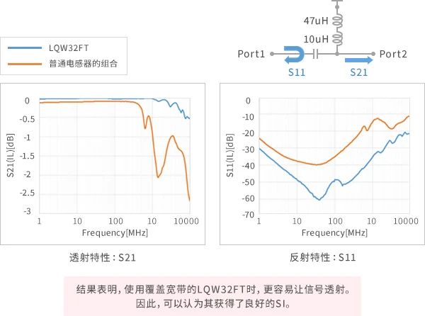
Signal line transmission characteristics (S21) and reflection characteristics (S11)
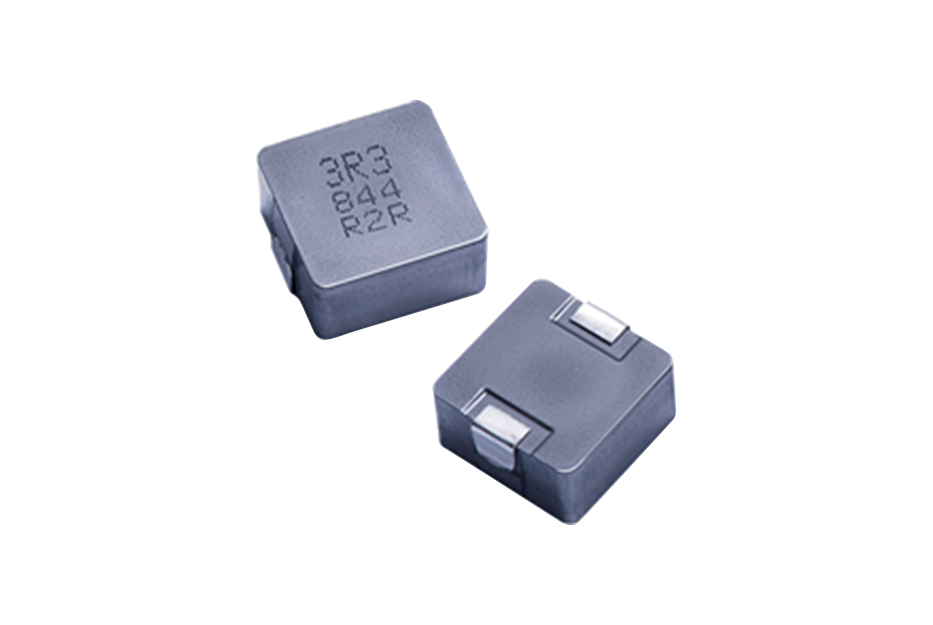
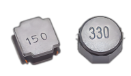
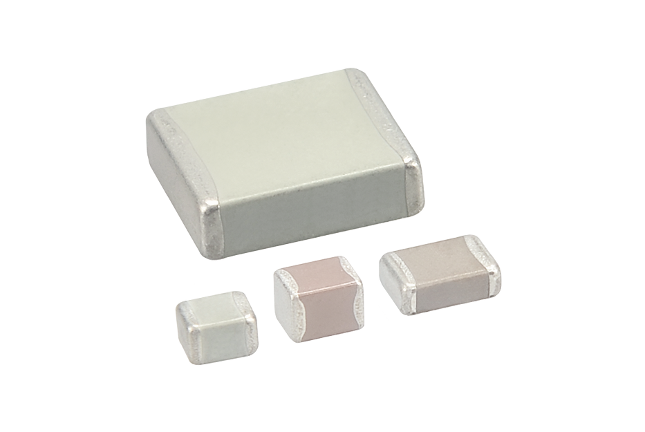
Recommended by Murata: Inductor (coil)

The impact of cables on SI
To confirm the impact of the characteristics of the onboard coaxial cable on the waveform, we let the signal from the signal generator flow through the onboard coaxial cable and observe the waveform using an oscilloscope. At the same time, we tested the transmission loss characteristics of the cable through S21. The measurement system is shown in the following figure.
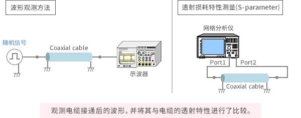
measurement system
After changing the cable length, it was found that the longer the cable, the more significant the decrease in high-frequency waveform quality (as shown in the figure below). This indicates that the impact of cables on SI cannot be ignored. When testing the Bias-T inductor, the S parameter must be confirmed through a testing system including cables.
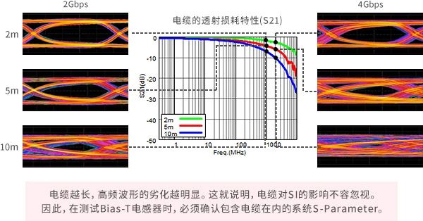
Transmission loss characteristics of cables (S21)
The impact of power noise on PoC systems:
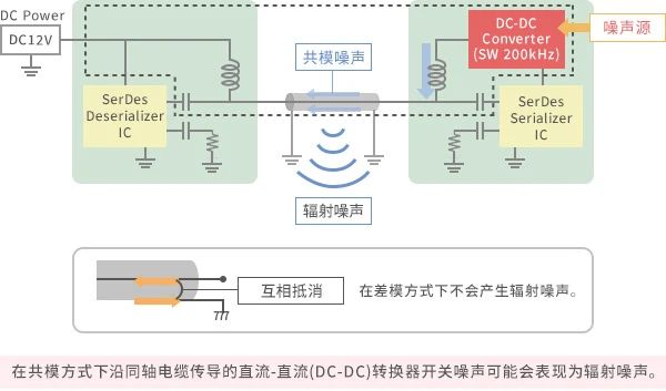
DC DC converters are typically used as power ICs for PoC circuits, but due to the high-speed switching of DC DC converters internally, switching noise may become a problem. The case of switch noise caused by direct current direct current (DC-DC) converters that can have adverse effects on PoC systems has been confirmed. Switching noise can be conducted through coaxial cables in both differential and common mode modes.
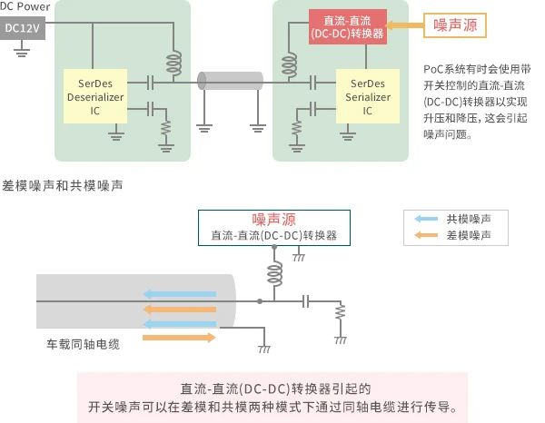
The PoC signal is transmitted in differential mode between the central conductor and the shielding layer of the coaxial cable. It can maintain good waveform quality without being affected by external noise. However, if switch noise enters the coaxial cable and is conducted in differential mode, the waveform quality may decrease (as shown in the figure below).
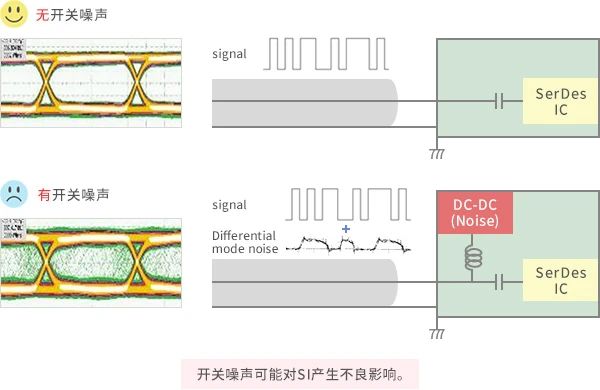
The impact of power supply noise caused by switches on SI
We have confirmed whether there is a difference in the SI (Signal Integrity) of the SerDes signal between the combination of multiple inductors and the LQW32FT developed for Bias-T.
When combining multiple inductors, the impedance curve is unstable, resulting in interference in the signal waveform. On the other hand, when using the LQW32FT series, the signal waveform is transmitted normally without interference.
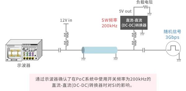
To confirm the impact of switch controlled DC DC converter noise, we connected the Bias-T inductor and coaxial cable to the DC DC converter and confirmed its impact on the waveform using an oscilloscope.
At this point, the signal source is 3Gbps and a DC DC converter with a switching frequency of 200kHz is used. The measurement system configuration is shown in the following figure.
The impact of power supply noise caused by measuring switches on SI
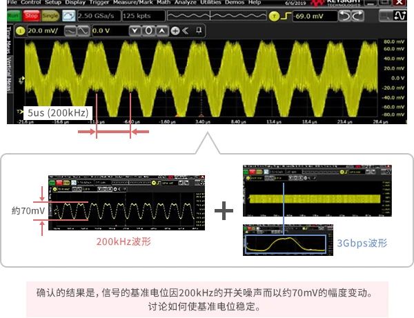
The following figure shows the waveform observed using an oscilloscope. Bias-T inductor: LQW32FT (10uH+47uH). The observed waveform is the combination of a high frequency of 3Gbps and a low frequency of 200 kHz. The reference potential of a 3Gbps signal varies in cycles of 200kHz. The fluctuation amplitude is about 70mV. Due to the potential negative impact of changes in the reference potential on communication, we discussed how to stabilize the reference potential.
In order to suppress 200kHz noise, we added a 100uH inductor LQH3NPH101MME where a Bias-T inductor was installed between the DC DC converter and the signal line. By adding a 100uH inductor in series to the Bias-T inductor, the impedance in the low-frequency region of about 200kHz can be increased.
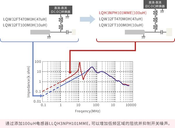
Reduce switch noise by adding Bias-T inductors
After changing the cable length, it was found that the longer the cable, the more significant the decrease in high-frequency waveform quality. This indicates that the impact of cables on SI cannot be ignored. When testing the Bias-T inductor, the S parameter must be confirmed through a testing system including cables.
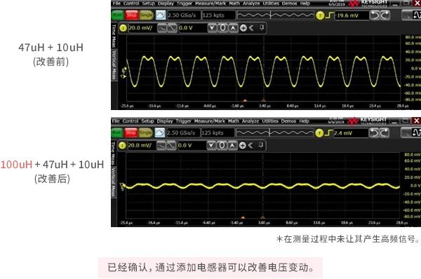
Improved results
Next, we consider the case where switching noise is conducted in a common mode between the central conductor and the shielding layer of a coaxial cable. Common mode noise often increases the level of radiated noise, so switching noise may cause radiated noise problems.
The impact of power supply noise caused by switches on radiated noise
To test the noise radiated by coaxial cables, we connect the substrate with a built-in direct current (DC-DC) converter and the substrate with a built-in Bias-T circuit using the following method, and connect the substrates equipped with a Bias-T circuit with coaxial cables to each other. Then, we use a current probe to measure the noise radiated from the coaxial cable. Due to the need to clamp the coaxial cable with a current probe, common mode noise was detected.
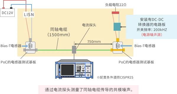
Let's take a look at the measurement results and analyze the specific impact of power supply noise caused by switches on radiated noise.
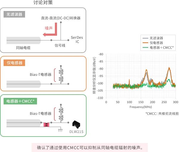
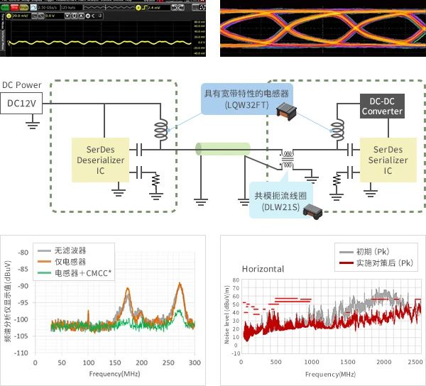
Firstly, as the Bias-T inductor is expected to function as a filter, we compared the noise measurement results without installing an inductor (without a filter) and with an installed inductor (only an inductor), but there was almost no change between the two. This may be because the Bias-T inductor is only effective against differential mode noise.
Next, in order to suppress the common mode noise conducted along the central conductor and shielding layer, a common mode choke coil (CMCC) was added, and it was found that the noise level could be suppressed by 5 to 10dB.
The impact of power supply noise caused by switches on radiated noise
Example of radiation noise countermeasures:
Next, we attempted to use a SerDes test substrate with a PoC system to measure radiated noise and adopted a noise reduction strategy. Connect the test substrates on the Tx side and Rx side using a 1.5 meter onboard coaxial cable, supply power to the Rx side, and measure the radiated noise during the operation of the test substrate.
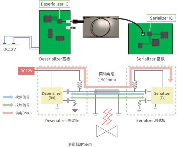
Test sample (DUT): SerDes test substrate
When measuring radiated noise, broadband noise was confirmed throughout the entire range of 30MHz to 2.5GHz, and there were frequency bands that exceeded the standard values (as shown in the figure below).
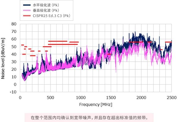
Initial state
In order to determine the noise source on the substrate, we conducted near-field distribution measurements on the surface of the substrate.
Broadband noise spectrum was observed on the signal line and IC power line of SerDes IC. In addition, when comparing the spectral shapes of the two, it was found that their values were different but their shapes were similar.
This indicates that the signal line and power line have the same noise source.
The signal line shows a high level, so the SerDes signal is likely to be a source of noise.
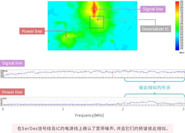
Measurement results of near magnetic field distribution
※Due to the fact that the DC DC converter on this test substrate is not a switch controlled type, the magnetic field distribution is not caused by switch noise。
The inferred noise transmission path is as follows.
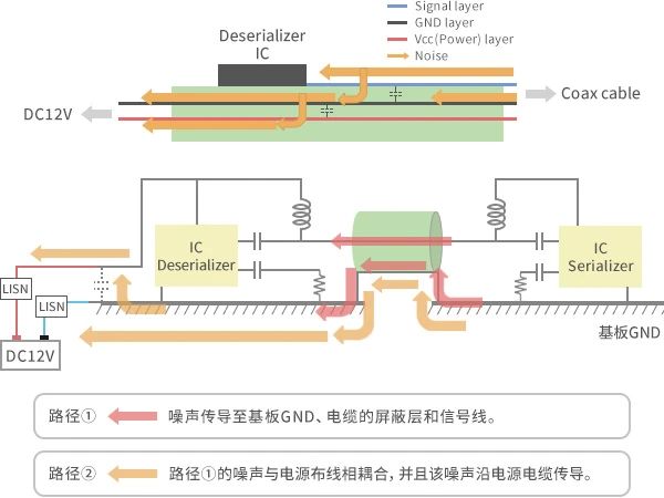
Noise transmission path from Serializer (speculated)
Path ①: Noise is transmitted to the substrate GND, the shielding layer of the cable, and the signal line.
Path ②: The noise in path ① is coupled to the power layer, and the noise is transmitted to the power cable.
The noise component of the signal sent from the Serializer IC is coupled to the GND layer on the substrate and conducted along the coaxial cable in a common mode manner. (Path ①)
The noise component is transmitted to the substrate equipped with Deserializer IC and is coupled to the power layer within the substrate, thereby conducting in a common mode along the power cable. (Path ②)
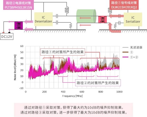
In order to implement countermeasures for path ①, a signal using CMCC DLW21SH391XQ2 was installed.
In order to implement countermeasures for path ②, CMCC - PLT5BPH5013R1SN for power supply was installed.
The results are as follows. Between 30MHz and 1000MHz, noise is suppressed by 10 to 20dB compared to the state without a filter.
30~1000MHz
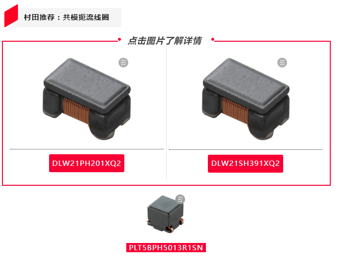
Here, the common mode choke coils recommended by Murata are PLT5BPH5013R1SN and DLW21SH391XQ2.
By adopting both strategies simultaneously (as shown in the figure below), the maximum suppression of noise is about 25dB in all frequencies from 30MHz to 2.5GHz.
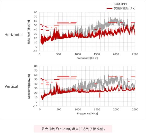
Countermeasures ①+②
Conclusion:
For the PoC system, the improvement of SI by Bias-T inductor and the suppression effect of CMCC on noise were verified.
By using inductors with broadband characteristics (LQW32FT series), SI has been improved.
Due to the significant impact of cables on SI, it is best to test the Bias-T inductor of the PoC system through the S parameter characteristics including cables.
The possibility of switching noise in direct current direct current (DC-DC) converters having adverse effects on SI was considered and verified. As a result, it was confirmed that the Bias-T inductor of PoC can reduce switching noise.
It has been confirmed that the switching noise and SerDes signal of the DC DC converter will become noise sources and may worsen the radiated noise level. It has been found that common mode choke coils (DLW21S series) are effective in solving this problem.
The products recommended by Murata in this case are: bias T inductor LQW32FT series, common mode choke coil PLT5BPH5013R1SN recommended by Murata, and DLW21SH391XQ2/DLW21PH201XQ2. The optimization results after using Murata's recommended products are shown in the following figure:
 4" />
4" />